From clearance to press fits; how to match tolerances with function.
1. How do you select the right ISO fit for real-life applications?
For engineers, the challenge isn’t understanding what H7/g6 or H7/p6 mean; it is about knowing when to use which.
In the real-world design, a fit isn’t just a tolerance value. It’s an important decision; Will the two parts slide smoothly, lock or seize, rotate freely as expected, or need to be removed and replaced often?
A slight clearance fit might be ideal for a rotating shaft of a motor. A tight interference fit might be the ideal option for a gear hub that must never move again. Choosing the right fit means balancing the intended function of the system, the assembly methodology, wear and tear, and efficient manufacturability.
Below are a few classic examples:

The old saying goes… No one size fits all. Your choice should be based on function first, and then assign tolerances accordingly.
2. What is the difference between Clearance, Transition, and Interference Fits?
ISO fits are grouped into three function categories:
- Clearance Fit: The shaft is always smaller than the hole. The parts assemble easily. Used for rotating or sliding parts that need low friction.
- Transition Fit: There may be slight clearance or slight interference. Depends on the exact sizes. Used for parts that must align precisely but do not need strong holding/frictional forces.
- Interference Fit: For example, a shaft may be larger than the hole it is intended for and requires press-fit or heat expansion for assembly. Used when the parts are intended not to move relative to each other. For example, a rotating gear-shaft assembly needing the gear to be pressed onto the shaft.
A quick visual reference for a shaft/gear assembly is below:

Think of it like this way… Clearance fits move, transition fits position, and interference fits stay put.
3. Should one tolerance the hole, the shaft, or both? Why is ‘H’ so common?
Take a look at almost any technical drawing, and you will see a familiar pattern: H7/h6, H7/g6, H7/p6…
Why is the hole always ‘H’? It’s design logic backed by manufacturing reality.
In the ISO system, ‘H’ means that the hole’s lower limit is exactly at the nominal dimension, and its tolerance is entirely in the positive direction. For example:
- H7 for Ø20 mm =20.000 to 20.021 mm
- It never measures below 20.000 mm, which means it is safe, simple, and predictable for tooling.
Why is that important?
- Most hole-making tools (drills, reamers, bores) produce standard sizes easily
- Holes are harder and more expensive to machine to tight tolerances
- Tooling libraries (especially for CNC and mass production) are already based on standard hole tolerances like H7
So instead of adjusting the hole to meet every use case, engineers leave the hole as H7 and modify only the shaft which is lower cost and easier to control.
In other words, “Let the hole stay constant. I’ll make the shaft fit the application”.
4. How does the assembly method affect tolerance selection?
Your choice of fit isn’t just about the function. It’s also about how the parts will be assembled. Let’s look at three common methods:
Manual assembly (hand-press or slide-in)
You will require a clearance fit (like H7/g6 or H7/f7). This allows smooth insertion without tools which is ideal for rotating shafts, pins, and bushings.
Press-fit (mechanical force)
You need an interference fit (like H7/p6 or H7/m6). A press is used to insert one part into another, and the fit is tight enough to resist slipping under designed level loads.
Thermal assembly (heating/cooling)
Used for strong interference fits when parts can’t be pressed easily such as a motor shaft/rotor assembly. One may have to heat the component with the hole and/or freeze the shaft to slide into position. Once the assembly cools down, the hole part contracts creating a tight fit between the parts.
Common terminology in gear installations or heavy-duty hubs.

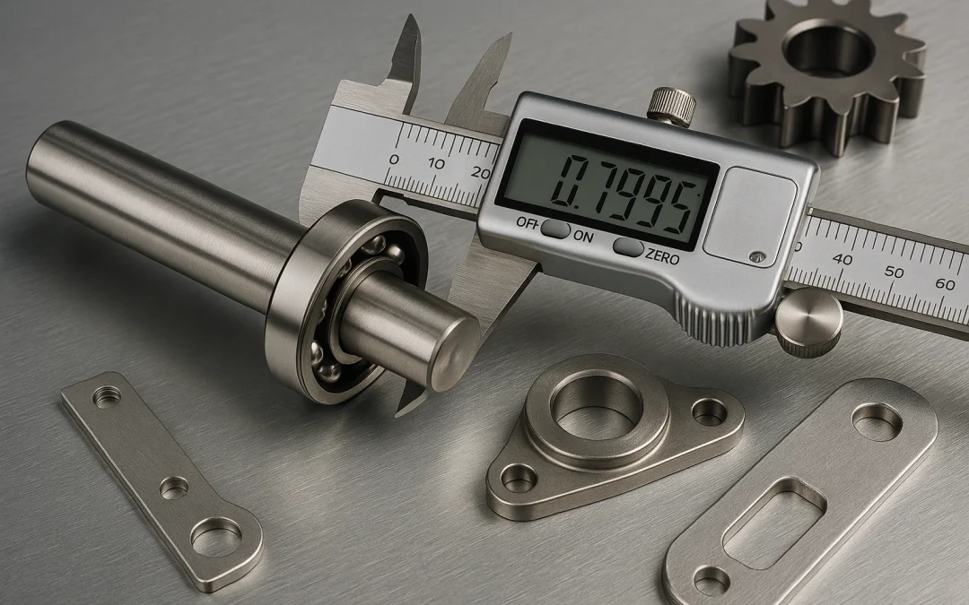
5. How do tighter tolerances affect manufacturing cost and precision?
Tighter tolerances may give the feeling of precision and safety “the tighter the range, the better the fit and therefore the better the performance,” right? Not quite.
Tight tolerances (such as g5 or h5) require:
- More accurate machines (often slower and more expensive to maintain)
- Greater tool wear and therefore more frequent tool changes adding costs
- Added quality control steps (e.g., CMM inspection, gauge verification)
All of the above raise costs, and sometimes exponentially while offering diminishing returns based on quality and function, if they are not truly needed.
Let’s put it this way:
Tight tolerances where they matter→ essential.
Tight tolerances everywhere → expensive and overkill.
Example: If a simple bracket hole is specified as H7, but the bolt going through it doesn’t require precise alignment, an H11 tolerance would work just fine and cost far less to produce.
6. What other factors affect tolerance selection?
Tolerancing isn’t just about size other technical realities matter as well:
Material Type
- Aluminum expands more than steel. Therefore a press-fit in aluminum needs to consider thermal expansion during the design process.
- Plastics may deform over time for any number of reasons and therefore using tight tolerances/fit may result in stress cracks and distortion.
Surface Finish
- A very tight fit (like interference) will not function properly if the surfaces are rough.
- Roughness can lead to micro-welding issues, wear and/or jamming.
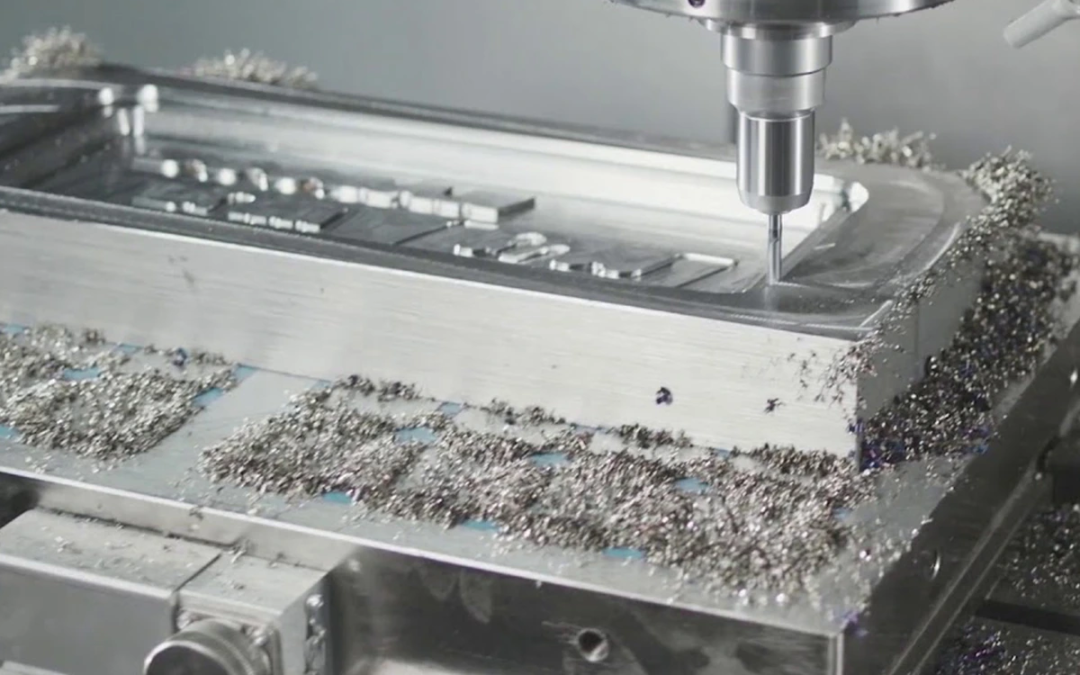
Manufacturing Method
- A turned shaft using a lathe may have different tolerance capabilities compared to a precision-ground shaft.
- Some tolerances may not even be possible or practical when using low-cost manufacturing methods.
These factors must be considered alongside fit type during the design process, not after.
7. What are the most common mistakes engineers make when choosing fit?
Even experienced engineers and designers fall into these traps:
Over tolerancing
Specifying unnecessarily tight tolerances out of habit or misinformation, without functional justification.
Result: Higher costs, longer lead times, greater part rejections.
Assuming parts from different suppliers will match or be consistent
Different manufacturing facilities interpret “nominal” and tolerances differently. Without clearly defining fits such as H7/g6, components from different facilities may result in mismatched assemblies.
Ignoring the assembly method
Designing a fit that theoretically works however is impossible to assemble with available tools or fixtures.
“Copy and Paste” from past drawings
Using a fit that worked once, without checking how things have progressed or how application have changed, can be disastrous for the final assembly.
The lesson: Every fit choice should answer this question.
“What does this part need to do, and how will it be made and assembled?”
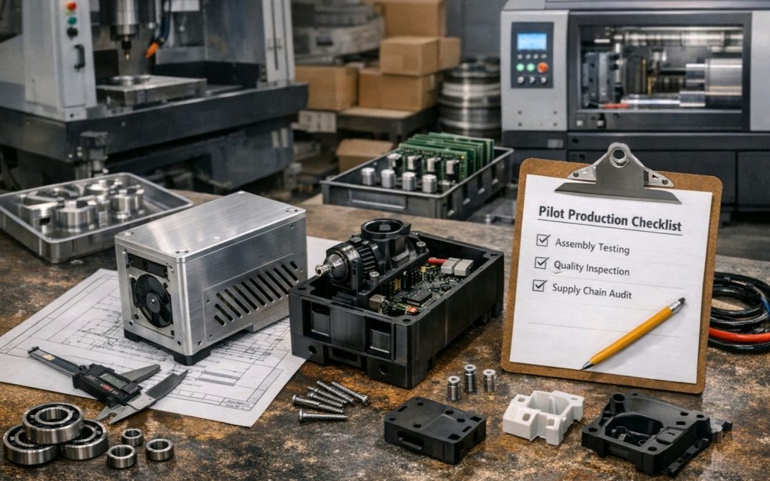
8. How can one ensure parts fit when multiple suppliers are involved?
In modern manufacturing, one often cannot control the complete production supply chain. A hole might be machined in Texas, and the shaft might be sourced from Germany. Even with top quality suppliers, inconsistencies can creep in especially when tolerances and instructions are vague or missing.
To ensure global interchangeability:
- Always specify fits explicitly using ISO notation (e.g., H7/g6, not just “Ø20 mm”)
- Avoid relying solely on nominal dimensions — suppliers may apply different default tolerances (DIN vs. ANSI vs. shop best practices)
- Use datum references and GD&T best practices when critical alignment is required
- Include both tolerance class and method in the drawing notes (e.g., “Shaft: ground to ISO 286 g6, per DIN 7160”)
Also, communicate clearly. If it’s a transition fit, state as such. If it must be a press-fit without fail, specify the required interference value.
Interchangeability isn’t just about drawing quality; it’s about shared understanding.
9. Which ISO fits are recommended for common mechanical components?
While every design is unique, decades of industrial best practices give us some excellent starting points. Here are practical fit suggestions based on application type:
Rotating Shafts in Bearings
- Fit: H7/g6 or H7/f7
- Why: Low friction, good guidance, easy assembly
- Used in: Motors, pumps, conveyors
Gear Hubs on Shafts
- Fit: H7/p6 or H7/m6
- Why: Requires press-fit for torque transmission
- Used in: Gearboxes, drive shafts
Dowel Pins for Precise Location
- Fit: H7/h6 or H7/js6
- Why: Precise alignment with minimal movement
- Used in: Fixture plates, locating pins
Pulley Mounts or Non-Critical Bushings
- Fit: H8/f8 or even H11/h9
- Why: Function over precision; looser fits reduce cost
- Used in: Agricultural equipment, HVAC systems
Shrink-Fit Assemblies
- Fit: H7/n6 or tighter
- Why: High holding force after thermal contraction
- Used in: Heavy-duty pressings, wheel hubs

These are suggestions and not hard rules. However, when in doubt, start here then adjust based on your specific functional, assembly, and cost needs.
A practical workflow for confident fit selection and why it pays off.
10. Is there a simple decision process to help choose the right fit?
Absolutely. While tolerance selection involves technical knowledge and judgement, a structured approach helps prevent overthinking and avoid costly mistakes.
Here’s a step-by-step framework to guide your fit selection:
Fit Selection Workflow
- What does the part do? Rotates? Slides? Aligns? Locks permanently?
- Is movement required after assembly? Yes → Consider clearance or transition fits No → Consider interference fit
- How will it be assembled? By hand? → Favor clearance With tools/fixtures? → Use interference Thermal methods? → Use tight interference
- Will the part be replaced or changed frequently? Yes → Avoid tight fits No → Interference fits are acceptable
- What is the application’s sensitivity to play or looseness? High sensitivity → Use tighter fit (g6, h6) Low sensitivity → Use looser fit (f7, h8, h9)
- Is precision alignment critical? Yes → Use transition fits like H7/h6 No → Clearance or loose fits acceptable
Example Use Case
Let’s say you are designing a motor shaft that turns at high speed inside a bearing.
- You want smooth rotation
- No binding or excessive play
- Easy assembly by hand
Recommended fit: H7/g6
Now take a gear hub mounted on a shaft where zero movement is allowed.
- You’ll use a press-fit
- Needs to transmit torque
- Permanent installation
Recommended fit: H7/p6