Introduction
Most engineers learn about tolerances in school often in theory, heavy lectures, with abstract examples and little context. But when you open a real drawing labeled H7/g6, the question becomes: What does this actually mean for the part I’m designing, machining, or assembling? This guide answers that and more.
1. What do the letters f, g, h, js, k, m, n, etc., actually mean in ISO fits?
These letters define the position of a tolerance zone in relation to the nominal (basic) size. ISO 286 assigns each letter to a specific shift above, below, or straddling the zero line.
– For shafts:
– f, g → clearance fits (below zero line)
– h → line to line (starts exactly at zero)
– j, k, m, n → interference fits (above zero)
– For holes:
– H is the most commonly used: zero line starts at the lower bound, all positive tolerance.
Think of the letter as the “vertical position” of the tolerance band on a chart. The number indicates its size (width).
2. What is the ISO system of limits and fits, and how does it differ from ANSI?
ISO (International System) uses a hole basis or shaft basis method with letter-number symbols. Example: H7/g6 → hole is H7, shaft is g6. The tolerances are chosen from standard tables based on nominal diameter.
By contrast, the ANSI (inch-based) system uses names like RC (Running Clearance), LC (Locational Clearance), or FN (Force Fit) instead of letters.
ISO | ANSI Equivalent
——————–
H7/g6 | RC5 – RC7
H7/h6 | LC or transition
H7/p6 | FN (press fit)
3. Why does the hole system usually use ‘H’, and shafts vary (f, g, h, etc.)?
Most tooling (reamers, drills, bores) produces standard hole sizes easily. So, designers fix the hole as H7, and only modify the shaft diameter to achieve desired fits.
Advantages:
– Interchangeability
– Tooling convenience
– Reduced cost (hole tolerance is standard, only the shaft varies)
That’s why you’ll often see things like:
– H7/h6 → transition fit
– H7/g6 → light clearance
– H7/p6 → interference/press fit
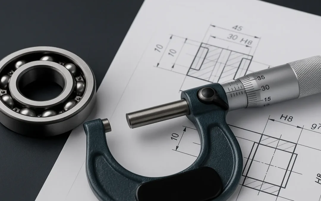
4. What does an H7/g6 fit mean in real world dimensions?
Let’s say your nominal shaft size is Ø20 mm.
According to ISO 286 tables:
– H7 hole → 0 / +0.021 mm ————- and then hole 20.000 mm to 20.021 mm
– g6 shaft → -0.007 / -0.020 mm ————- and then shaft 19.980 mm to 19.993 mm
So:
– Minimum clearance: 20.000 − 19.993 = 0.007 mm
– Maximum clearance: 20.021 − 19.980 = 0.041 mm
In simpler terms: the shaft will always be slightly smaller than the hole, ensuring it always fits in without force. Depending on the tolerance shift, the clearance can range from very snug (0.007 mm) to quite loose (0.041 mm).
This range is why H7/g6 is called a “sliding” or “light clearance” fit. It allows for easy assembly and low friction movement ideal for parts like rotating shafts, pins, or bushings where too much play isn’t acceptable, but tight force-fit isn’t necessary either.
5. How are these fits selected based on function?
Fit Type | Symbol Example | Description
———–|———————–|————
Clearance Fit | H7/g6, H8/f7 | Shaft always smaller than hole. Free movement.
Transition Fit | H7/h6, H7/js6 | May have slight clearance or interference. Precise location.
Interference Fit | H7/p6, H7/m6 | Shaft larger than hole. Requires press or heat assembly.
Use clearance fits for rotating shafts, pulleys.
Use interference fits for gears, hubs, and press-in pins.
Use transition fits where alignment is critical (e.g., dowel pins, bearing seats).
6. How are tolerance values calculated from fit symbols?
Tolerance bands are defined in the ISO 286-1 and 286-2 standards. You don’t calculate them manually unless needed; just use standard tables.
However, you should know:
– Letter sets the position of the band (offset from nominal)
– Number sets the width of the band (based on IT grade)
Example for Ø20 mm:
– H7: 0 / +0.021 mm → width = 0.021 mm
– g6: -0.007 / -0.020 mm → width = 0.013 mm
7. How does shaft/hole size affect tolerance bands?
As the nominal diameter increases, the tolerance band widens even if the fit type stays the same (e.g., H7/g6).
Nominal Ø | H7 Tolerance (mm) | g6 Tolerance (mm)
————–|—————————|——————-
10 mm | 0 / +0.015 | -0.006 / -0.016
20 mm | 0 / +0.021 | -0.007 / -0.020
50 mm | 0 / +0.033 | -0.010 / -0.030
8. What’s the impact of choosing the wrong fit?
Real world consequences:
– Too tight:
- Assembly damage
- Seized parts
- Thermal expansion cracking
– Too loose:
- Wobble, misalignment
- Noise/vibration
- Premature bearing or gear failureA project I worked on once had a bearing bore spec’d at H7 instead of H6. It led to micro-fretting and destroyed a $40,000 test rig in two weeks.Tolerances may look like decimals on paper but they’re thousands of dollars in practice.
Common ISO Fits and Their Typical Applications
| HOLE BASIS FIT | SHAFT BASIS FIT | FIT TYPE | APPLICATION EXAMPLES |
| H7/s6 | S7/h6 | Press Fit | Gears, flywheels, hubs requiring permanent press fit |
| H7/p6 | P7/h6 | Press Fit (Locational Interference Fit) | Shrink fits for pulleys and rigid couplings |
| H7/k6 | K7/h6 | Locational Press Fit | Locational press fits for hubs, bearings |
| H7/h6 | h6/H7 | Locational Clearance Fit | Tight alignment dowel pins, coupling flanges |
| H7/g6 | G7/h6 | Sliding Fit | Rotating shafts with low friction |
| H8/f7 | F8/h7 | Running Clearance Fit (tight) | Medium speed shafts, bearing seats with minor play |
| H8/f8 | F8/h8 | Running Clearance Fit (normal) | Standard motor mounts, pump housings |
| H8/h9 | h9/H8 | Loose Clearance Fit | Bolted assemblies, bushings with high tolerance |
| H9/d9 | D9/h9 | Very Loose Fit | Welded tube joints, clearance holes for bolts |
| H11/c11 | C11/h11 | Non-critical Clearance Fit | Sheet metal assemblies, non-load-bearing parts |